
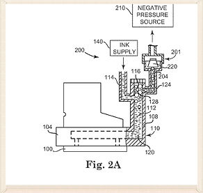
A liquid delivery system and method move an air impermeable membrane (32) adjacent a liquid chamber in response to withdrawal of liquid from the chamber (50) to move a plunger (42, 242). The plunger (42, 242) moves between a first position fluidly connecting a fluid source (16) and a fluid actuated valve (14) to open the valve (14) and supply liquid to the liquid chamber (50) and a second position blocking connection of the fluid source (16) and the fluid actuated valve (14).

An ink supply system including a reservoir and a foam regulator. The reservoir is configured to hold a volume of ink and configured to be in fluid communication with a fluid ejection structure. The foam regulator is operable in a first state in which the foam regulator permits application of negative pressure through the foam regulator to apply negative pressure to the fluid ejection structure and to the reservoir, and a second state in which the foam regulator blocks passage of ink foam through the foam regulator.
An apparatus is to selectively purge a desired fluid-jet printhead of a number of fluid-jet printheads of a page-wide array fluid-jet device. The apparatus includes a purging insert movably locatable within a fluid channel of the page-wide array fluid-jet device. The fluid channel is to supply fluid to the fluid-jet printheads during normal operation of the page-wide array fluid-jet device. The apparatus includes a movement mechanism operatively coupled to the purging insert to move the purging insert within the fluid channel incident to the desired fluid-jet printhead. The apparatus includes a pressurizing mechanism fluidically coupled to the purging insert to pressurize fluid. The purging insert is to deliver the fluid as pressurized by the pressurizing mechanism to the desired fluid-jet printhead to purge the desired fluid-jet printhead.

A method for white ink delivery includes circulating white ink through a white ink delivery system between successive print jobs; and in response to a time interval between two of the successive print jobs being greater than a threshold time interval, draining the white ink from the white ink delivery system

In one embodiment, a non-contact print head cleaning device includes an elongated cavity underlying a print head and a vacuum port connected to the elongated cavity and generating a low pressure in the elongated cavity. A slot in a wall of the elongated cavity has a geometry that varies along its length to produce an airflow with a substantially uniform velocity into the slot. The airflow sucks contaminants off the print head into the slot. A method for non-contact print head cleaning is also provided.
The method of operating an inkjet printing system includes ejecting usable fluid on a substrate in a print mode and in a purge container in a maintenance mode by a print head. The method also includes receiving recovered fluid from the purge container and source fluid from the source supply to form the usable fluid in a primary fluid tank. The method also includes receiving and providing an amount of the usable fluid from the primary fluid tank to the print head by at least one of a first supplemental fluid tank and a second supplemental fluid tank. The method also includes determining a consumed amount of the usable fluid corresponding to an amount of the usable fluid used by the print head reduced by an amount of the recovered fluid received by the primary fluid tank from the purge container.

A method of maintaining an inkjet print head device (10) includes applying a first set of maintenance signals by a control unit (15) to a first set of actuators (11a) of an inkjet print head device. The first set of maintenance signals applied by the control unit causes movement of the first set of actuators to move meniscuses of a first set of fluid channels (12a) in fluid communication with the first set of actuators, respectively, between an expansion state and a retraction state without fluid droplets ejecting from the first set of fluid channels. The method also includes applying a second set of maintenance signals by the control unit to the first set of actuators of the inkjet print head device. The second set of maintenance signals applied by the control unit cause movement thereof to circulate fluid in the first set of fluid channels without the fluid droplets ejecting from the first set of fluid channels

An apparatus includes a tank for holding a fluid for delivery to a printhead, the tank being open to the atmosphere. A manifold enables the fluid to flow from the tank to the printhead, a height of the manifold being lower than a level of the fluid in the tank when the fluid is flowing from the tank to the printhead. A siphon has a lower end of the siphon that is connectable to the manifold. An upper end of the siphon extends above the level of the fluid and is openable to the atmosphere. A height of a segment of the siphon between the upper end and the lower end is lower than the height of the manifold.

A fluid applicator mounting device includes a main body to removeably receive a fluid applicator module. The main body includes a common fluid channel having a main input port, a main output port, a supplemental input port to provide fluid to the fluid applicator module, and a supplemental output port to output fluid from the fluid applicator module. The fluid applicator mounting device also includes an input fin member disposed inside the common fluid channel and arranged proximate to the supplemental input port to guide fluid to the fluid applicator module. The fluid applicator mounting device also includes an output fin member disposed inside the common fluid channel and arranged proximate to the supplemental output port to guide fluid from the fluid applicator module away from the supplemental output port.

In one embodiment, an actuator connected to a printhead structure is activated with a waveform to cause vibration of the structure sufficient to move fluid within a printhead channel adjacent to the structure and not cause the fluid to eject from the channel during a nonprinting period. In another embodiment, a first pulse module applies a pulse at a printhead structure at a combination of voltage, duration, and frequency to cause shaking of printhead structure to move fluid within a printhead channel adjacent to the structure without ejecting the fluid from the channel during a nonprinting period. In another embodiment, an actuator connected to a printhead structure is activated during a nonprinting period to pulse the structure to move fluid within a printhead channel adjacent to the structure without causing the fluid to be expelled from the channel
